Dr-power Chipper User Manual
Browse online or download User Manual for Gardening equipment Dr-power Chipper. DR Power Chipper User Manual
- Page / 32
- Table of contents
- TROUBLESHOOTING
- BOOKMARKS
Rated. / 5. Based on customer reviews
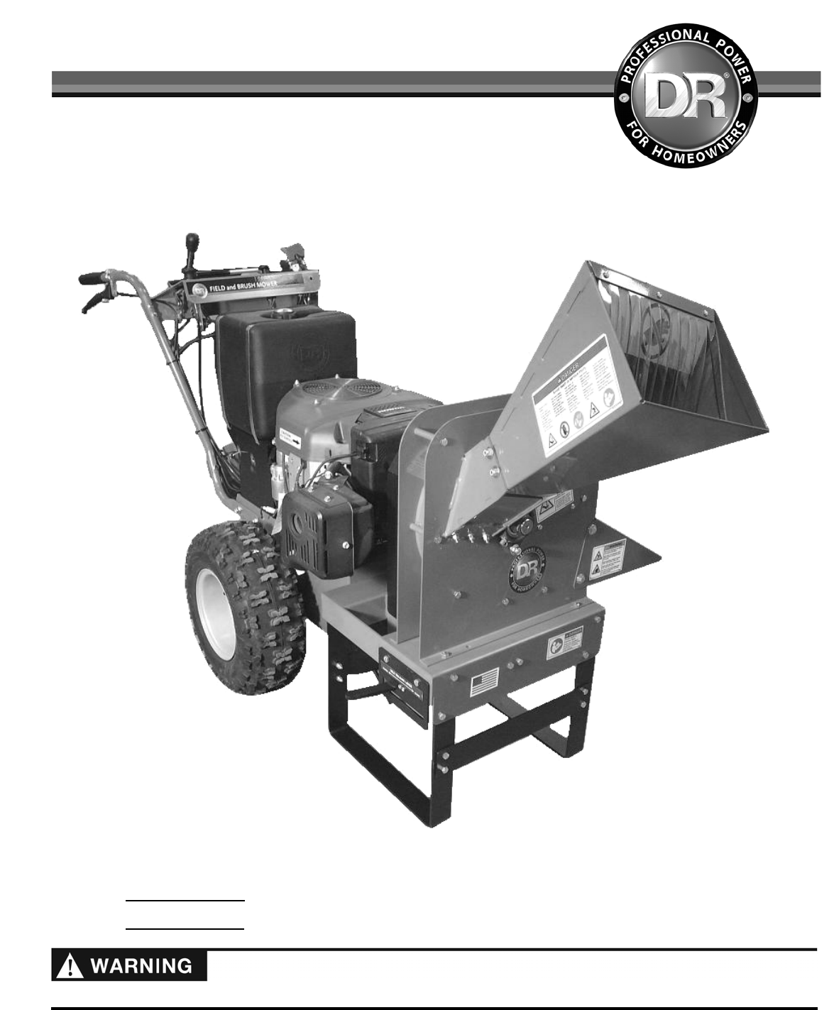
Read and understand this manual and all instructions before operating the DR Chipper Attachment.
D
R
®
CHIPPER ATTACHMENT for the
DR
®
FIELD and BRUSH MOWER
SAFETY & OPERATING INSTRUCTIONS
Serial No.
Order No.
DR Power Equipment
Toll-free phone: 1-800-DR-OWNER (376-9637)
Fax: 1-802-877-1213
Web site: www.DRpower.com
- Serial No 1
- Order No 1
- Table of Contents 2
- Safety for Children and Pets 4
- General Safety 5
- Specifications 7
- TEM # DESCRIPTION QTY 8
- ATM123741 to ATM126369) 9
- Newer Field and Brush Mower 10
- Older Field and Brush Mower 11
- Installing the Relay 11
- ATM126369) 13
- Starting the Chipper 14
- Processing Material 15
- Stopping the Chipper 15
- Operation Notes 15
- To Free a Jammed Flywheel 16
- Grease Fittings 18
- 5/16" Wrench 19
- Replacing the Belt 24
- Troubleshooting Table 26
- YMPTOM POSSIBLE CAUSE 27
- Parts List – FRAME ASSEMBLY 28
- Schematic – FRAME ASSEMBLY 29
- Parts List – CHIPPER BASIC 30
- Schematic – CHIPPER BASIC 31
- End of Season and Storage 32
Summary of Contents
Page 1 - Order No
Read and understand this manual and all instructions before operating the DR Chipper Attachment. DR® CHIPPER ATTACHMENT for the DR® FIELD and BRUSH
Page 2 - Table of Contents
10 DR® CHIPPER ATTACHMENT 8. Plug in the Blade Control, Key Switch and Operator Presence Connectors of the new Harness (Figure 11). 9. Ro
Page 3
CONTACT US AT www.DRpower.com 11 3. Connect the two Connectors of the Chipper Harness to the Operator Presence Connectors (Figure 15). 4.
Page 4 - Safety for Children and Pets
12 DR® CHIPPER ATTACHMENT Mounting the Chipper Attachment to the Field and Brush Mower 1. Remove the Deck or other attachment from the Fiel
Page 5 - General Safety
CONTACT US AT www.DRpower.com 13 7. Position the Belt onto the Field and Brush Mower Pulley (Figure 24) and then route it over the two Idle
Page 6
14 DR® CHIPPER ATTACHMENT Chapter 3: Operating Your DR CHIPPER ATTACHMENT Operating the Chipper Attachment It may be helpful to familiarize
Page 7 - Specifications
CONTACT US AT www.DRpower.com 15 Operator Zone Discharge Area Operator Zone Figure 30 Top View Hopper Chipper Field and Brush Mower Stopping
Page 8 - TEM # DESCRIPTION QTY
16 DR® CHIPPER ATTACHMENT The Chipper is designed to accept wood only. The Chipper Knife mounted on a revolving flywheel turns branches fed
Page 9 - ATM123741 to ATM126369)
CONTACT US AT www.DRpower.com 17 2. Remove the two Bolts, four Washers and two Locknuts that secure the Deflector to the Chipper Assembly w
Page 10 - Newer Field and Brush Mower
18 DR® CHIPPER ATTACHMENT Chapter 4: Maintaining The DR CHIPPER ATTACHMENT For DR Field and Brush Mower maintenance, please refer to the Saf
Page 11 - Installing the Relay
CONTACT US AT www.DRpower.com 19 2. Wipe all dirt, etc., from the grease fittings with a clean cloth (Figure 32). 3. Apply no more than th
Page 12
2 DR® CHIPPER ATTACHMENT This indicates a hazardous situation, which, if not avoided, could result in death or serious injury. Table of Cont
Page 13 - ATM126369)
20 DR® CHIPPER ATTACHMENT 1. Remove the four Screws that secure the Front Access Cover with a 5/16" wrench and remove the Access Cover
Page 14 - Starting the Chipper
CONTACT US AT www.DRpower.com 21 3. Rotate the Flywheel using a long stick until the three countersunk Allen Screws and Locknuts attaching
Page 15 - Operation Notes
22 DR® CHIPPER ATTACHMENT Disengage the blade at the control panel of the Field and Brush Mower. Shut down the engine, wait for all moving p
Page 16 - To Free a Jammed Flywheel
CONTACT US AT www.DRpower.com 23 After any knife or wear plate maintenance or adjustment, rotate the chipper flywheel by using a wooden stic
Page 17
24 DR® CHIPPER ATTACHMENT Wear Plate Sharpening The Wear Plate edges become rounded and chipped during use and must be squared off to ensure
Page 18 - Grease Fittings
CONTACT US AT www.DRpower.com 25 5. Position the Belt onto the Field and Brush Mower Pulley (Figure 47) and then route it over the two Idle
Page 19 - 5/16" Wrench
26 DR® CHIPPER ATTACHMENT Chapter 5: Troubleshooting Most problems are easy to fix. Consult the Troubleshooting Table below for common probl
Page 20
CONTACT US AT www.DRpower.com 27 Troubleshooting Table (Continued) SYMPTOM POSSIBLE CAUSE Engine will not run unless Operator Presence lever
Page 21
28 DR® CHIPPER ATTACHMENT Chapter 6: Parts Lists and Schematic Diagrams Parts List – FRAME ASSEMBLY NOTE: Part numbers listed are available
Page 22
CONTACT US AT www.DRpower.com 29 Schematic – FRAME ASSEMBLY
Page 23
CONTACT US AT www.DRpower.com 3 Chapter 1: General Safety Rules Labels Your DR CHIPPER ATTACHMENT carries prominent labels as reminders for
Page 24 - Replacing the Belt
30 DR® CHIPPER ATTACHMENT Parts List – CHIPPER BASIC NOTE: Part numbers listed are available through DR Power Equipment. Ref# Part# Descrip
Page 25
CONTACT US AT www.DRpower.com 31 Schematic – CHIPPER BASIC
Page 26 - Troubleshooting Table
75 MEIGS ROAD, P.O. BOX 25, VERGENNES, VERMONT 05491 ©2013 Country Home Products, Inc. All rights reserved 257241A Daily Checklist for the DR CHIPPE
Page 27 - YMPTOM POSSIBLE CAUSE
4 DR® CHIPPER ATTACHMENT Protecting Yourself and Those Around You Safety for Children and Pets This is a high-powered machine, with moving p
Page 28 - Parts List – FRAME ASSEMBLY
CONTACT US AT www.DRpower.com 5 General Safety Additional Information and Potential Changes DR Power Equipment reserves the right to discont
Page 29 - Schematic – FRAME ASSEMBLY
6 DR® CHIPPER ATTACHMENT Figure 1 Discharge Chute Hopper Chipper Knife Access Cover (Both Sides) Belt Guard Belt Tighten/Release Lever Blow
Page 30 - Parts List – CHIPPER BASIC
CONTACT US AT www.DRpower.com 7 Specifications MECHANICAL SPECIFICATIONS Driven by DR Field and Brush Mower (V-Belt and Clutch) Chipping Cap
Page 31 - Schematic – CHIPPER BASIC
8 DR® CHIPPER ATTACHMENT 7. Cut open the Parts Box with a Utility Knife and remove the contents (Figure 5). 8. Remove the Bubble Wrap from
Page 32 - End of Season and Storage
CONTACT US AT www.DRpower.com 9 Note: You may need to use a soft faced hammer to carefully tap the Bolts through the holes in the next step.
Related products and manuals for Gardening equipment Dr-power Chipper
Gardening equipment Dr-power Walk-behind 13 - 17 HP (April 2005 - August 2005) User Manual
 (54 pages)
(54 pages)
Gardening equipment Dr-power Walk-behind 13 - 17 HP (May 2001 - February 2003) User Manual
(36 pages)
(36 pages)
Gardening equipment Dr-power Self-Propelled Pro-XL Self-Propelled 8.26fpt Subar User Manual
(40 pages)
(40 pages)
© 2020, manymanuals.com. All rights reserved. | 0.953 s |
 Manymanuals.com
 Manymanuals.de
 Manymanuals.fr
 Manymanuals.it
 Manymanuals.pl
 Manymanuals.cz
 Manymanuals.es
 Manymanuals-pt.com
Comments to this Manuals